| Main Technical Conditions Of Twist Drill |
|
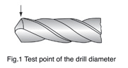
| Drill diameter |
| The values indicated in the relevant dimensional standards apply in respect of the diameter of Twist Drills. |
| Test point: On the lands at the corners,(see Fig.l) |
|
|
|
|
|
| Testing equipment: micrometer |
|
| Tapering of diameter |
| The diameter of twist drills usually reduces from the drill tip towards the shank in the area of the flutes. |
| Test values:The taper on diameter amounts to 0.02 to 0.08mm over a length of 100mm. |
| Test point: At the outside diameter on the land. |
| Testing equipment: micrometer and indicating measuring instruments. |
|
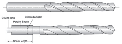
| Parallel shank |
| Tolerance for shank diameter f11,Tolerance for roundness and parallelism 0.02mm for the shank length. |
|
| Concentricity tolorance(Tr.) |
| The concentricity tolerance(Tr.) of the Twist Drill is calculated from the equation. |
| Tr=O.03+O.O11/d |
| In which I is the total length and d the diameter of the drill (all dimensions in mm) |
|
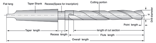
| Length |
| The tolerance of length for the total length corresponds for the degree of accuracy very coarse according |
| to DIN 7168 part 1.The flute lengths given in the relevant dimensional stands are minimum dimensions. |
|
|
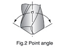
| Point angle |
| Test value:σ=118°;σ135° |
| Test point: At the cutting edges(See Fig.2) |
| Testing equipment: Universal bevel protractor indicating measuring instruments. |
|
|
|
|
|
|
| Materials and hardness |
|
| Materials |
| M2; M35i M42; F4341; 93410r4341; |
|
| Hardness |
| HSS HRC63-66 |
| HSSCO HRC64-68 |
| Test point: On outside diameter on the land or adjacent relieved land. |
| Test equipment: Hardness Tester. |
|
| Making |
|
| Twist drills with diameter 3mm and upwards shall be marked with: |
| Diameter |
| Material:(HSS;HSSCO;) |
| Name or mark of manufacturer. |
| Additional and/or differing marking by agreement. |
|
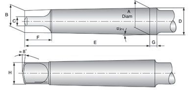
| Twist Drill with parallel shank |
|
|
|
|
|
|
|
|
|
| Twist Drill with taper shank |
|
|
|
|
|
|
|
|
|
| General dimensions of morse taper shanks |
|
|
|
|
|
|
|
|
|
|
|
| Morse Taper Shank |
A mm |
B mm |
C(h13) mm |
D mm |
E mm |
F(max.) mm |
G mm |
H(max.) mm |
α/2 |
| No.1 |
12.065 |
9 |
5.2 |
12.2 |
62 |
13.5 |
3.5 |
8.7 |
1°25’43 |
| NO.2 |
17.78 |
14 |
6.3 |
18 |
75 |
16 |
5 |
13.5 |
1°25’50 |
| NO.3 |
23.825 |
19.1 |
7.9 |
24.1 |
94 |
20 |
5 |
18.5 |
1°26’16 |
| NO.4 |
31.267 |
25.2 |
11,9 |
31.6 |
117.5 |
24 |
6.5 |
24.5 |
1°29’15 |
| NO.5 |
44.399 |
36.5 |
15.9 |
44.7 |
149.5 |
29 |
6.5 |
35.7 |
1°30’26 |
| NO.6 |
63.348 |
52.4 |
19 |
63.8 |
210 |
40 |
8 |
51 |
1°29’36 |
|
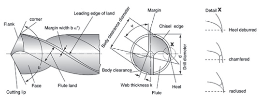
| Cutting portion |
 |
|
|
|
|
|
|
|
|
|
|
|
| σ= Point angle (sigma) |
| ψ = Chisel edge angle(psi) |
| *)In the context of cutting technology, land width b is the body clearance land width which is to be by bfan see |
| DIN 6581. |
|
| Angle at the cutting edges |
|
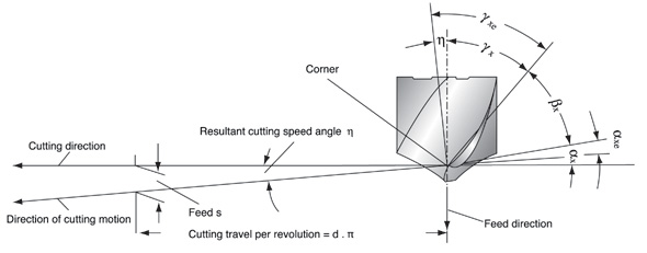 The corner has been adopted as the observed edge point The corner has been adopted as the observed edge point |
|
|
|
|
|
|
|
|
|
|
|
|
| αx=Side clearance angle (alpha) |
| αxe=Effective side clearance angle |
| βx=Side wedge angle(beta) |
| γx=Front rake angle(gamma) |
| γxe=Working front rake angle |
| η=Resultant cutting speed angle(eta) |
|
| Clearance angle α,wedge angle β and rake angleγare measured in the tool orthogonal plane. For details, |
| see DIN 6581, definitions of metal-cutting technology; geometry at the tool edge. |
|
|
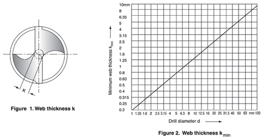
| Web thickness K |
|
| Test values:The web thickness according to Fig.1 shall not be less than the minimum value kmin indicated in Fig.2. |
| Test point: At the point of the drill. |
| Testing equipment:Slide gauge with measuring points. |
|
|
|
|
|
|
|
|
|
|
|
|
|
|
|
|
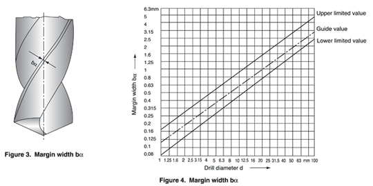
| Margin width bα |
|
| Test values: The land width as in Fig.3 shall lie within the limitting values indicated in Fig.4 |
| Test point: 5mm behind the corner |
| Testing equipment: Slide gauge |
|
|
|
|
|
|
|
|
|
|
|
|
|
|
|
| Angle on twist drills |
|
| (1)Side rake angle γf (Helix angle) |
| Recommended test value: Recommended ranges depending on the tool types N,H and W according to DIN 1836 |
| and the diameter of the drill included in Fig.5 |
| Test point: At the corner, see Fig.6 |
| Testing equipment: According to VDI Guideline 3331 Part1 ,Section Margin widthbα |
| Note:The side rake angle γfis measured in place of the orthonagonal rake angle γo found in the wedge measuring |
| plane(see DIN 6581),as this changes along the cutting edge(becoming smaller towards the point of the drill) |
|
|
|
|
|
|
|
|
|
|
|
| (2) Point angle σ |
| test value: Usual executin for tool types N and H:σ =118°,for tool type W:σ =130° |
| Test point: At the cutting, see Fig.7. |
| Testing equipment: According to VDI Guideline 3331 Part 1, Section Margin width bα |
|
|
| Resharpening Twist drills |
|
|
|
|
|
|
|
|
|
|
|
| (1) Drills are worn off irregularly.It should be sharpened prior to developing into excessive wear. |
| (2) Resharpening |
| ①Grind the correct point angle to suit your application.(figure 8) |
| ②Check that both cutting lips have the same angle. On a 130° point,each lip should be 65° toward the axis. |
| The point must be on center, i.e.,the chisel edge must produce cutting lips of equal length.(figure 8) |
| ③Grind Primary relief and Secondary clearance,(figure 9) |
| ④Grind web thinning.(figure 10) |
|
| Web Thinning |
|
|
|
|
|
|
|
|
|
|
|
| (1) Without thinning |
| Suitable for drill of general purpose.Thanks to thin web thickness, web thinning is not need. |
| This without web thinning type is applied to design of drills for mild steel, alloy steels, cast iron, stainless steel, |
| titanium, inconel, etc. and conventional cutting conditons. |
|
|
|
|
|
|
| (2) Type C thinning (DIN 1412 FORM C,SPLIT POINT) |
| Because Split point enables good centering |
| when drilling and breaks the chips,chip removals is easy. |
| Suitable for drill design in high hardened tough materials,i.e, heat treated steel, titanium alloy, stainless steel, |
| incoroy inconel, nimonic, etc. |
|
|
|
|
| (3) Type R thinning (HEI.ICAL THINNING) |
| Helical thinning ensure to frequent chip breaking and removal. The different direction force of cutting edges and |
| helical thinning parts enables that chips curl, break and remove through the flutes. In addition helical thinning |
| makes the chip room up to center, remove the chisel and enables good centering. |
|
|
|
|
| (4)Type A thinning (DIN1412 FORM A) |
| A type thinnings makes thin chisel, good chip removal and favorable centering. |
| This type is the easiest type to grind the thinning. In narrow web and wide fluted drills,keeping of the rigidity and |
| smooth chip removal are possible. |
|
|
|
|
| (5) Type B thinning (DIN1412 FORM B) |
| In case of work materials with low cutting resistance and good chip removal,ie,cast iron,aluminium, plastic etc, B |
| type thinning is suitable. Especially when drills for high hardended steels are designed, this type is applied to |
| decrease rake angle and avoid chipping of cutting lips. |
|
|
|
|
| The Industry`s Most Verstile Deep Hole Drill |
| |
|
|
|
| The wide land parabolic design provides greater strength and rigidity while wllowing move |
|
| flute area to accommodate chip flow.The stronger cross section allows to handle a wider |
|
|
| variety of medium to heavy-duty applications.The benfits of the design include; |
|
|
| Improved coolant flow to point |
|
|
| Reduced machining time;less retooling and downtime |
|
|
|
|
| Closer hole tolerances |
Length |
| Reduced torque levels |
Jobber |
| Reduced chip congestion |
Screw Machine |
| Deep Hole drills are offered in a length, material and finish for your application |
Taper |
| Refer to the Technical Data (pgs. 14-15) for oPerating parameters. |
Extra Length |
| |
|
|
|
|
| Construction Comparison |
|
|
|

|
|
|
|
|
|
|
|
|
|
| |
|
|
|
|
|
|
|
|
|
| Deep Hole Drills |
Finish |
Material |
| 135° split point |
Surface Treated |
HSS |
| Increased flute area allows more room for chip evacuation |
Bright |
HSS |
| Reduced margin width reduces heat generation |
TiN Coated |
HSS |
| Wider land provides increased strength and rigidity |
BRONZE |
COBALT |
| Performs best in alloyed steels |
TIIALN |
COBALT |
|
|
|
|
|
|
|
|
|
| |
|
|
|
|
|
|
|
|
| |
|
|
|
|
|
|
|
|
| Standard Parabolic Drills |
|
|
|
| 135° split point |
|
|
|
| Standard parabolic flute area |
|
|
|
| Standard margin |
|
|
|
| Narrow land |
|
|
|
|
| Performs best in mild steels |
|
|
|
| |
|
|
|
|
| 135° Split-Point, Heavy-Duty, TiN-Coated |
|
|
|
|
|
|
|
|
| |
|
|
|
|
| |
|
|
|
|
| Size |
Decimal Equivalent |
Flute Length |
Overall Length |
Env. Qty. |
| 1/16 |
0.0625 |
7/8 |
1/16 |
12 |
| 5/64 |
0.0781 |
1 |
5/65 |
12 |
| 3/32 |
0.0938 |
1-1/4 |
3/32 |
12 |
| 7/64 |
0.1094 |
1-1/2 |
7/64 |
12 |
| 1/8 |
0.1250 |
1-5/8 |
2-3/4 |
12 |
| 9/64 |
0.1406 |
1-3/4 |
2-7/8 |
12 |
| 5/32 |
0.2188 |
2 |
3-1/8 |
12 |
| 11/64 |
0.1719 |
2-1/8 |
3-1/4 |
12 |
| 3/16 |
0.1875 |
2-5/16 |
3-1/2 |
12 |
| 13/64 |
0.2031 |
2-7/16 |
3-5/8 |
12 |
| 7/32 |
0.2188 |
2-1/2 |
3-3/4 |
12 |
| 15/64 |
0.2344 |
2-5/8 |
3-3/7 |
12 |
| 1/4 |
0.2500 |
2-3/4 |
4 |
12 |
| 17/64 |
0.2656 |
2-7/8 |
4-1/8 |
12 |
| 9/32 |
0.2812 |
2-15/16 |
4-1/4 |
12 |
| 19/64 |
0.2969 |
3-1/16 |
4-3/8 |
12 |
| 5/16 |
0.3125 |
3-3/16 |
4-1/2 |
6 |
| 21/64 |
0.3281 |
3-5/16 |
4-5/8 |
6 |
| 11/32 |
0.3438 |
3-7/16 |
4-3/4 |
6 |
| 23/64 |
0.3594 |
3-1/2 |
4-7/8 |
6 |
| 3/8 |
0.3750 |
3-5/8 |
5 |
6 |
| 25/64 |
0.3906 |
3-3/4 |
5-1/8 |
6 |
| 13/32 |
0.4062 |
3-7/8 |
5-1/4 |
6 |
| 27/64 |
0.4219 |
3-15/16 |
5-3/8 |
6 |
| 7/16 |
0.4375 |
4-1/16 |
5-1/2 |
6 |
| 29/64 |
0.4531 |
4-3/16 |
5-5/8 |
6 |
| 15/32 |
0.4688 |
4-5/16 |
5-3/4 |
6 |
| 31/64 |
0.4844 |
4-3/8 |
5-7/8 |
6 |
| 1/2 |
0.5000 |
4-1/2 |
6 |
6 |

|
|
|
|
|
| |
|
|
|
|
| |
|
|
|
|
| |
|
|
|
|
| |
|
|
|
|
| Material Application Chart |
|
|
|
| |
|
|
|
|
| Finish |
Range of Application details |
|
|
|
| Black/Bronze Oxide |
Iron,Steel,Stainless Steel,Wood |
|
|
|
| |
|
|
|
|
|
|
|
|
|
| 135 Split-Point for quick penetration and reduced walking |
| Premium-grade M-7 industrial steel and super hard performance coating for longer, heat resistance and easier drilling |
| Unique flute design for superior material removal |
| Heavy-duty construction provides additional strength |
| Designed for enhanced performance in medium-and high-tensile strength alloy materials |
| |
|
|
|
|
|
|
|
|
|
| Size |
Flute Length |
Overall Length |
|
|
|
|
|
| 0.5 |
22 |
6 |
|
|
|
|
|
| 1 |
34 |
12 |
|
|
|
|
|
| 1.5 |
40 |
18 |
|
|
|
|
|
| 2 |
49 |
24 |
|
|
|
|
|
| 2.5 |
57 |
30 |
|
|
|
|
|
| 3 |
61 |
33 |
|
|
|
|
|
| 3.5 |
70 |
39 |
|
|
|
|
|
| 4 |
75 |
43 |
|
|
|
|
|
| 4.5 |
80 |
47 |
|
|
|
|
|
| 5 |
86 |
52 |
|
|
|
|
|
| 5.5 |
93 |
57 |
|
|
|
|
|
| 6 |
93 |
57 |
|
|
|
|
|
| 6.5 |
101 |
63 |
|
|
|
|
|
| 7 |
109 |
69 |
|
|
|
|
|
| 7.5 |
109 |
69 |
|
|
|
|
|
| 8 |
117 |
75 |
|
|
|
|
|
| 8.5 |
117 |
75 |
|
|
|
|
|
| 9 |
125 |
81 |
|
|
|
|
|
| 9.5 |
125 |
81 |
|
|
|
|
|
| 10 |
133 |
87 |
|
|
|
|
|
| 10.5 |
133 |
87 |
|
|
|
|
|
| 11 |
142 |
94 |
|
|
|
|
|
| 11.5 |
142 |
94 |
|
|
|
|
|
| 12 |
151 |
101 |
|
|
|
|
|
| 12.5 |
151 |
101 |
|
|
|
|
|
| 13 |
151 |
101 |
|
|
|
|
|
|
|
|
|
|
|
|
|
|
|